
Professional manufacturers
Vertical turbine pumps,sump pumps,right angle gearboxes
+8613974960765
+8618507312158
Working Days:9:00-22:00
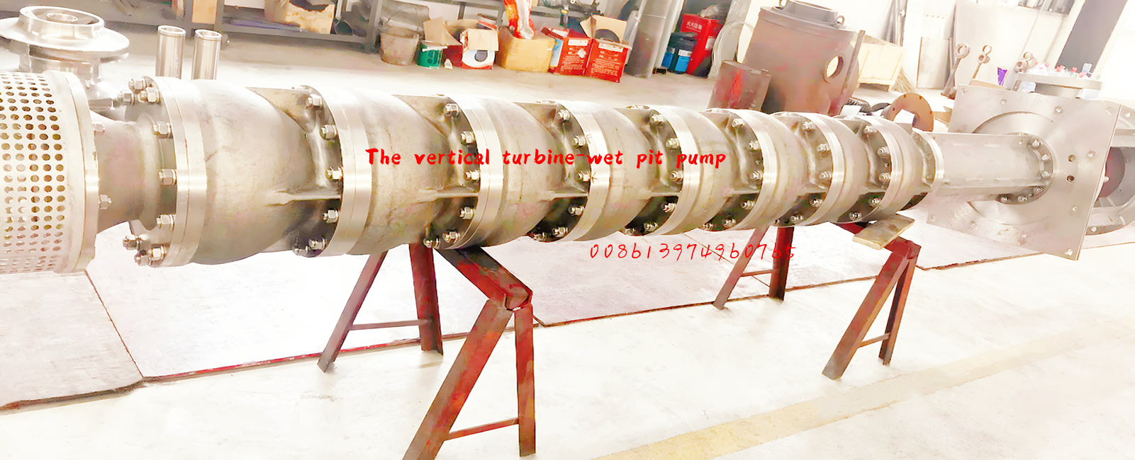
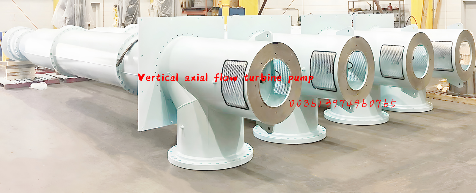
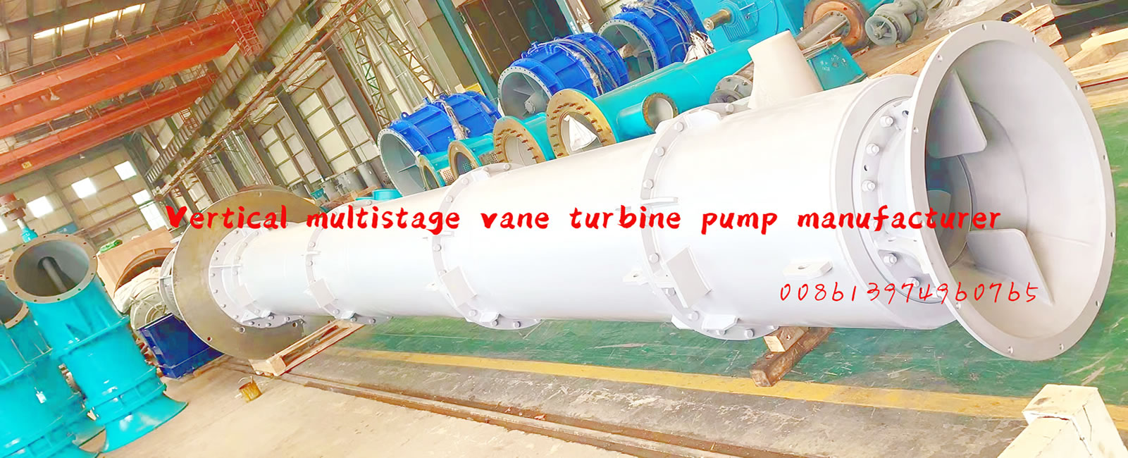
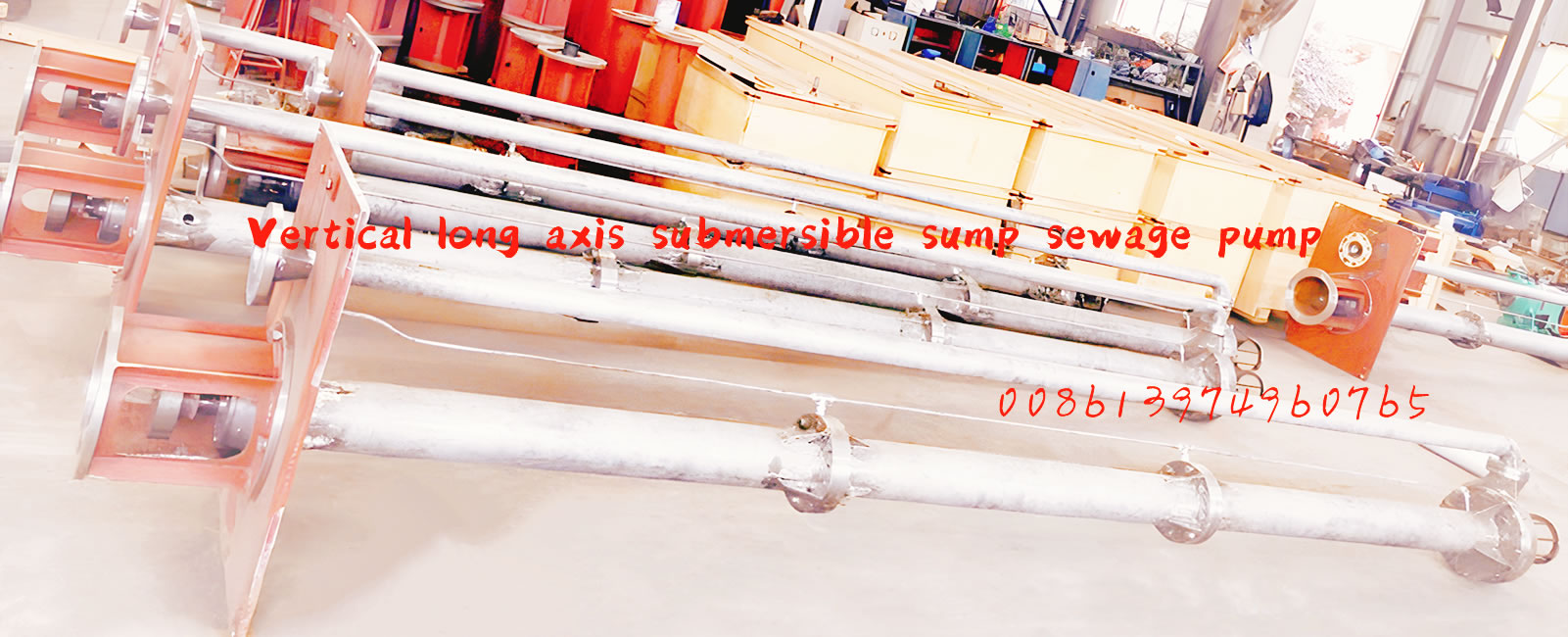
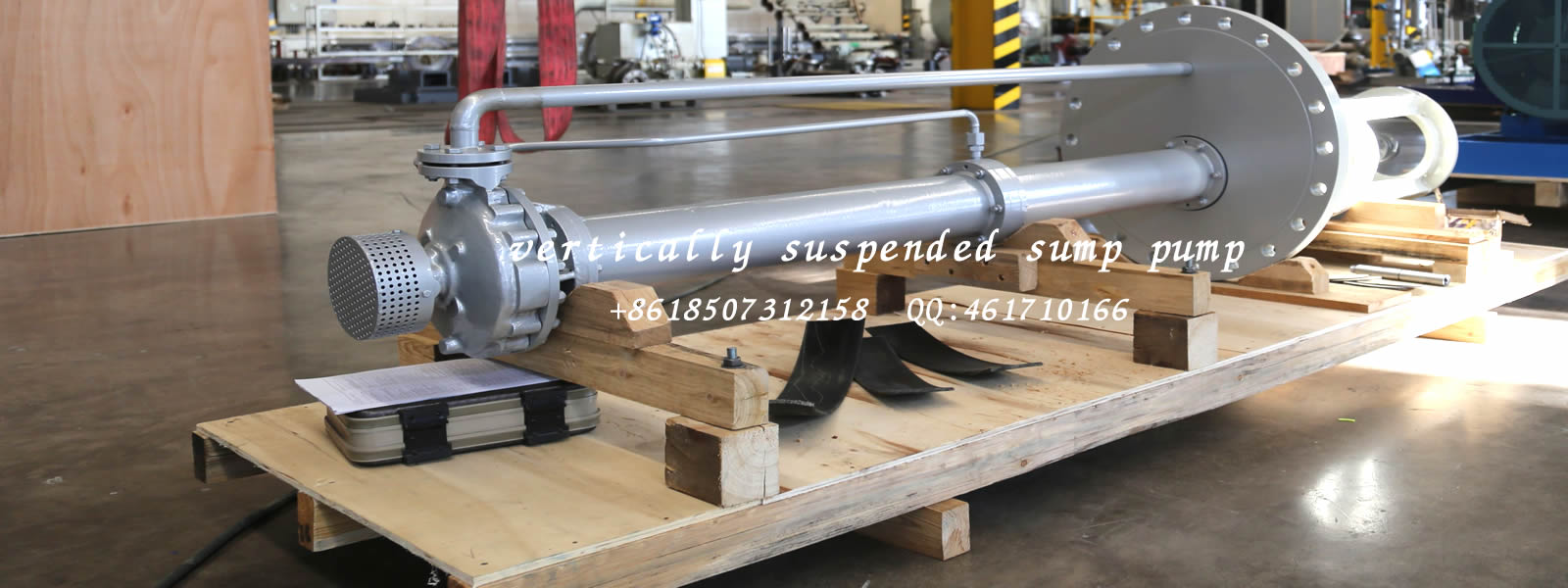
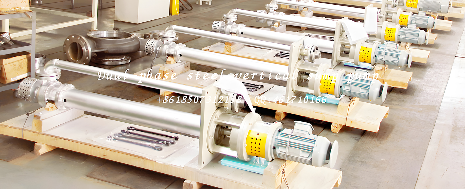
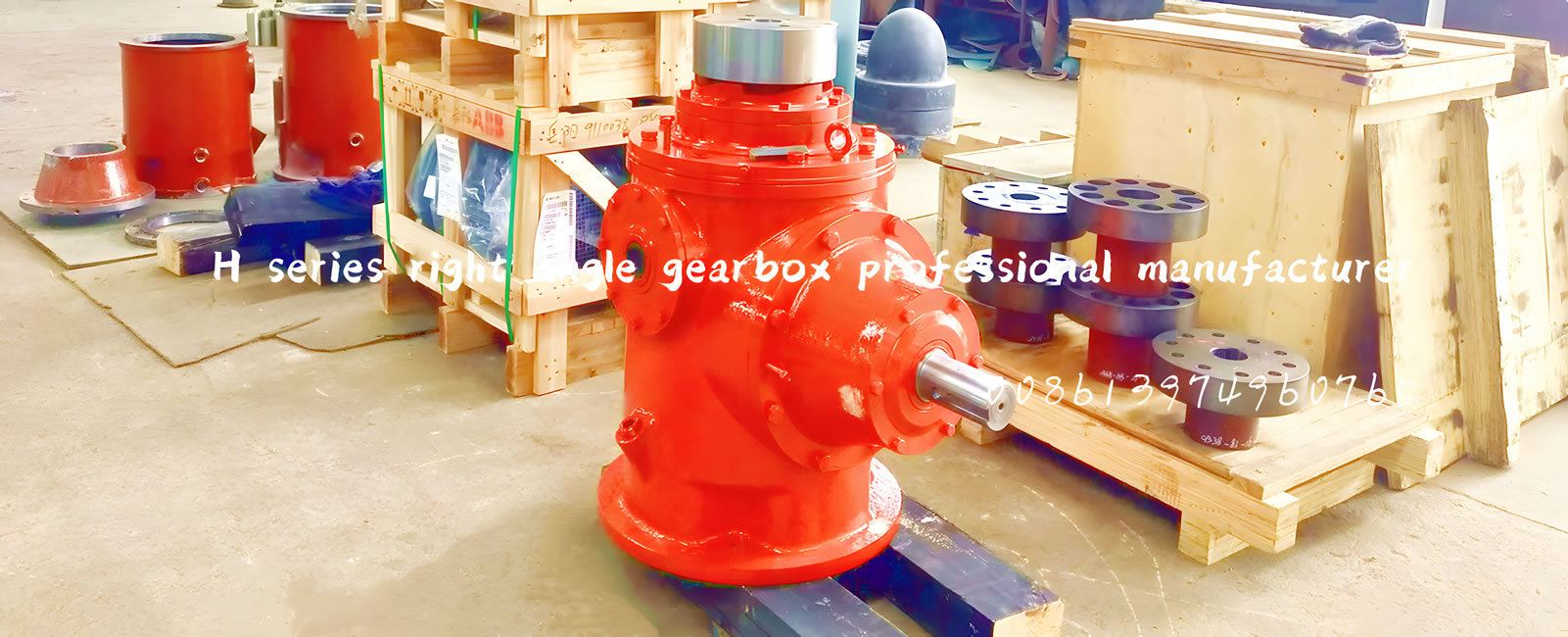
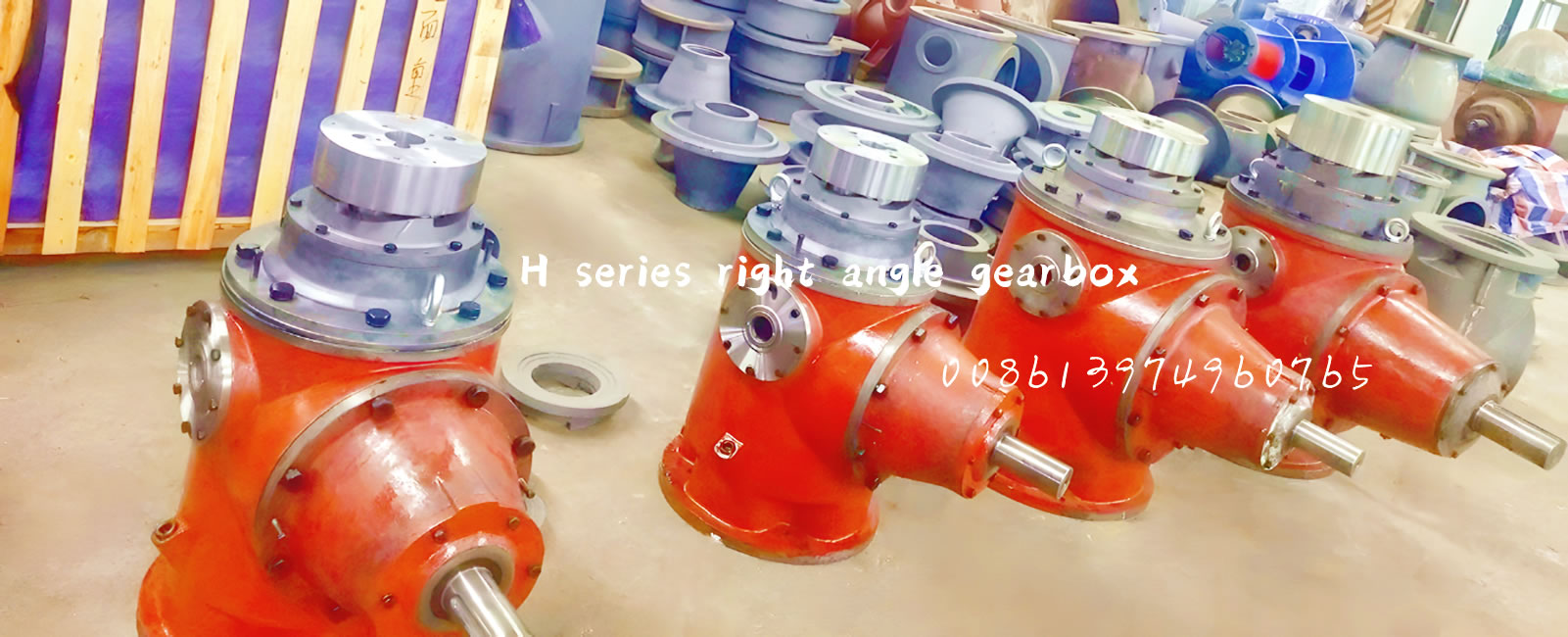
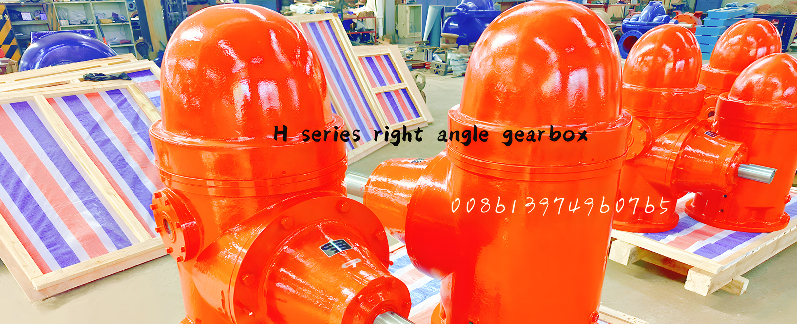
Our products: vertical turbine pump, vertical wet pit pump, vertical oil sump pump, vertical condensation pump, right Angle gearbox
Vertical turbine pumps,sump pumps,right angle gearboxes
Working Days:9:00-22:00
DATE:2023/2/13 10:41:29
浏览次数:
1. Genereal
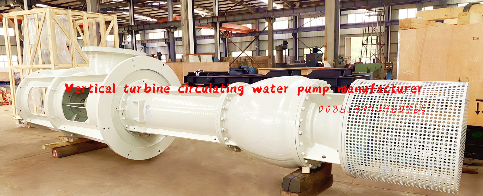
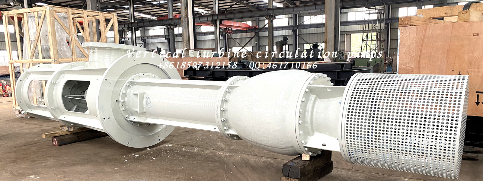
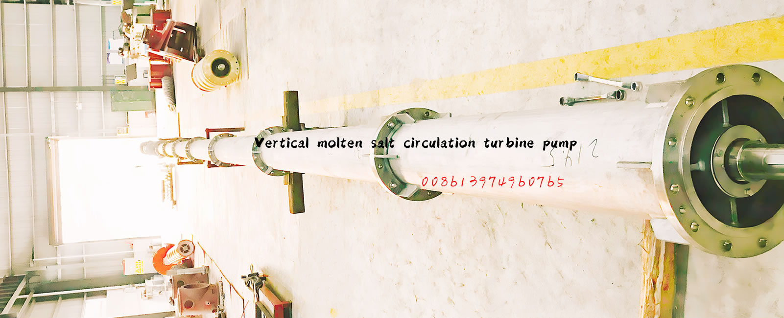
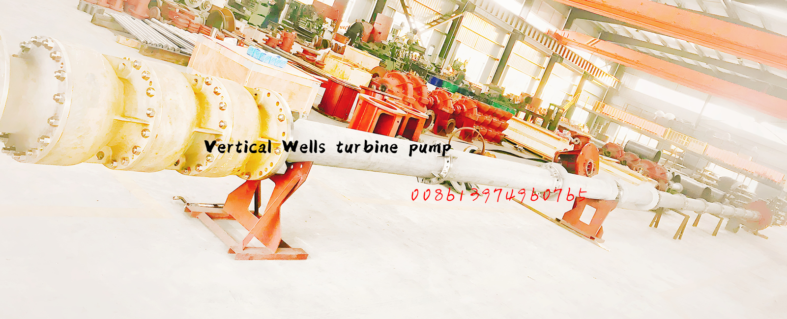
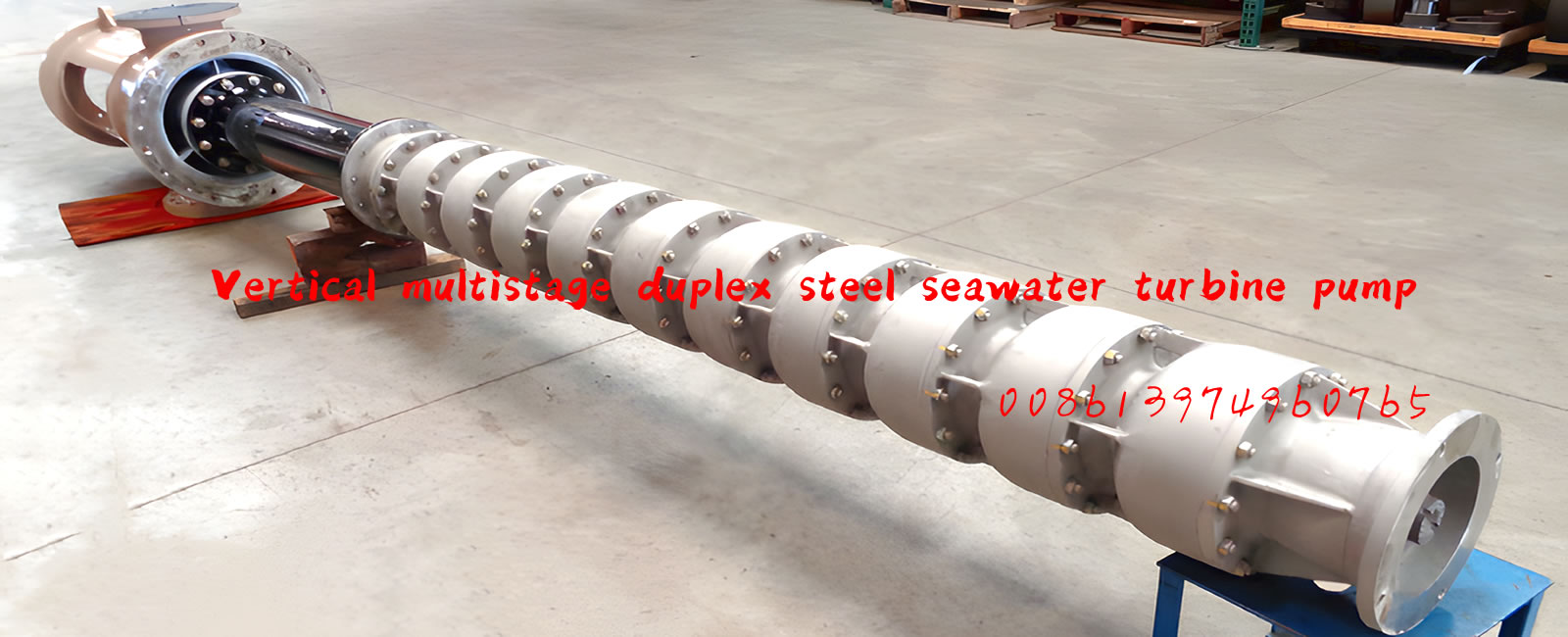
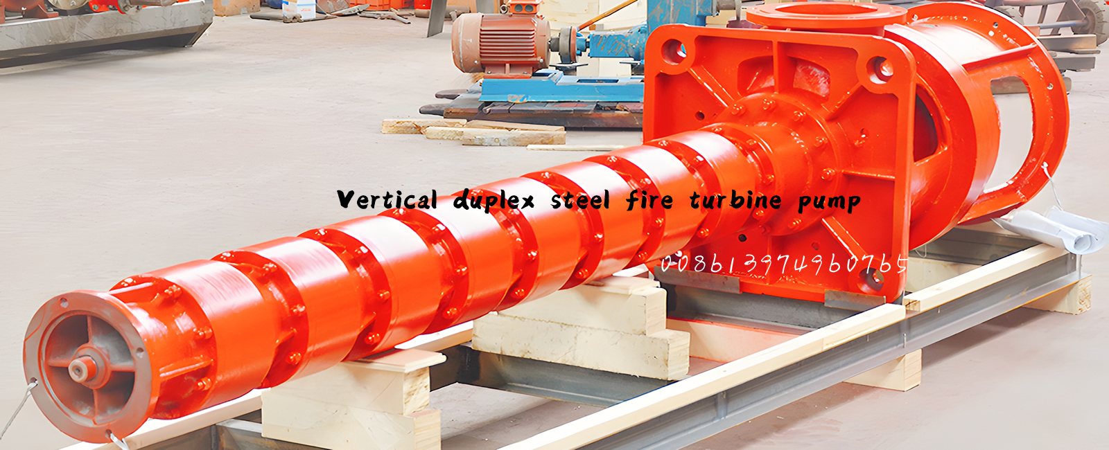
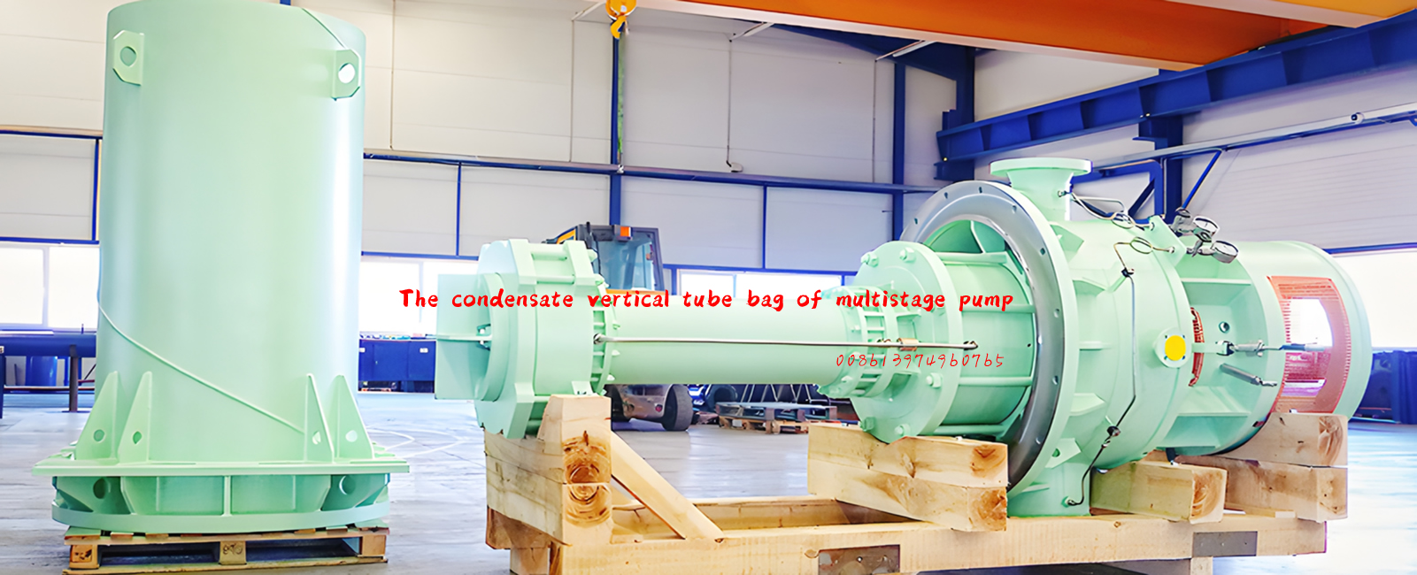
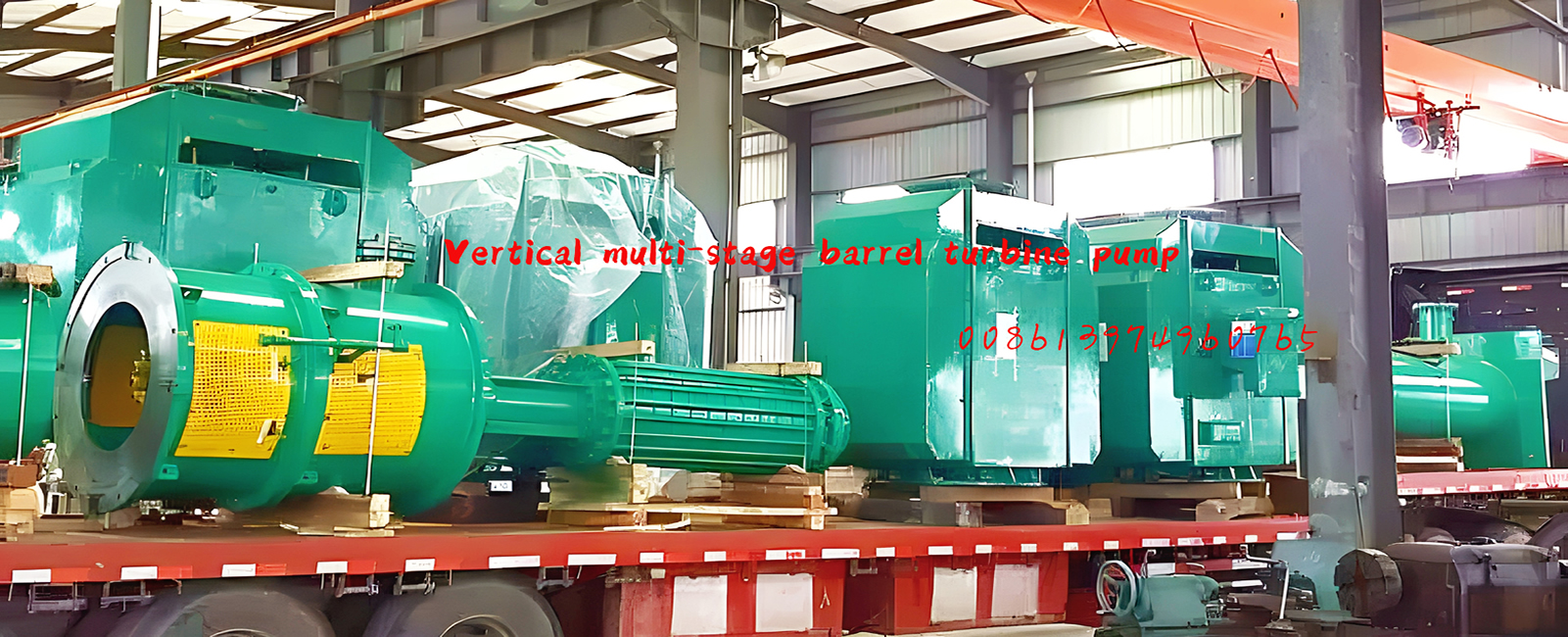
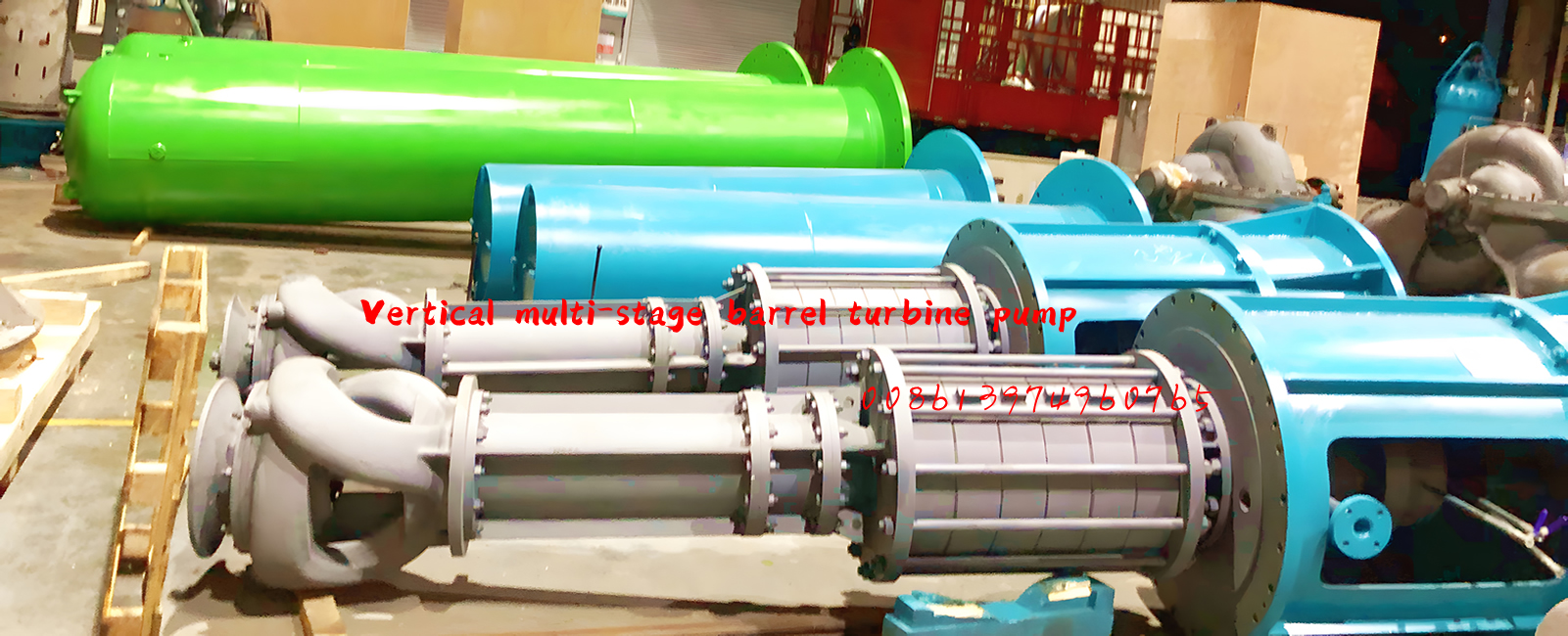
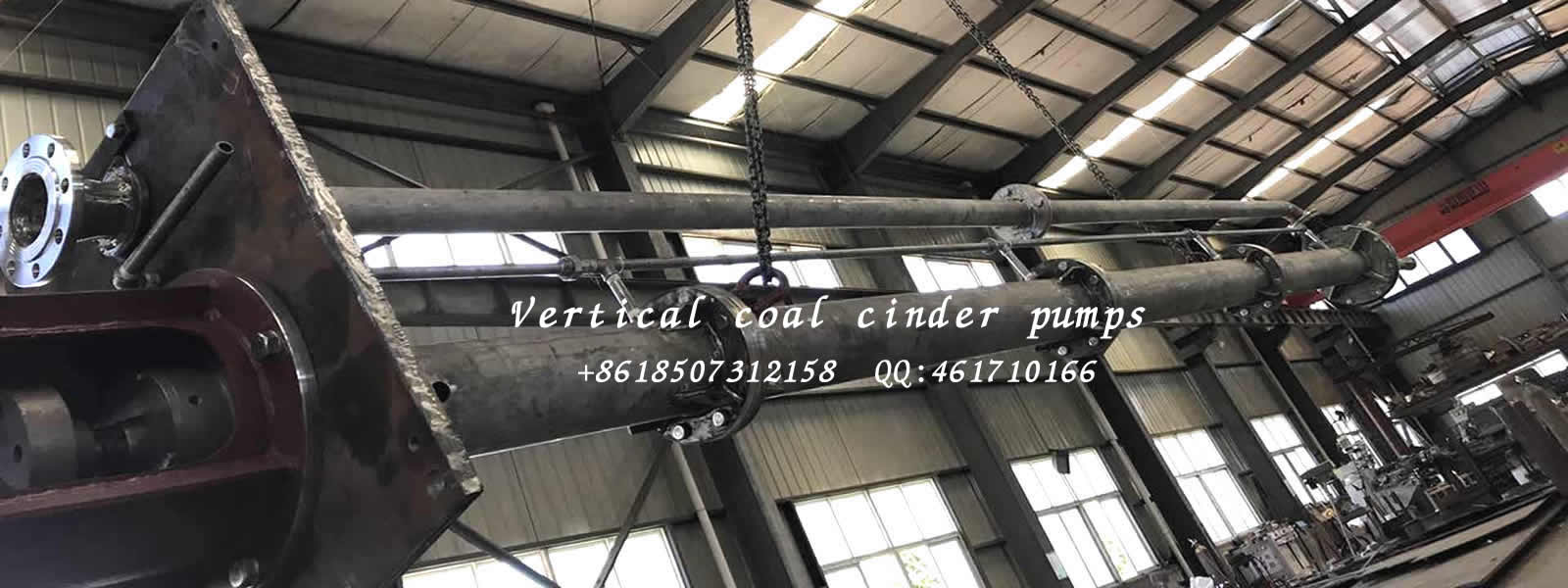
Vertical Cryogenic Process Pump is a special kind of multistage centrifugal pump, is energy efficient products of our company according to the market demand for independent development, carefully designed, with high efficiency, cavitation performance, advanced structure, long service life and convenient installation and maintenance etc.. Applicable to the transport of condensate and other liquids similar to condensate.
1.1 Performance range
Speed: 1480 r/min
Flow rate: 120 ~ 2200m3/h
Lift: 36 ~ 500m
1.2 Working conditions
Medium temperature:less than or equal to 80℃,special material can reach 120℃
Direction rotation: turn counterclockwise from the drive side.
1.3 Model significance
200JLDTN-485
200 - outlet diameter 200mm
JLDTN -- Vertical Cryogenic Process Pump
485 - designed head at 485m
2. Structure description
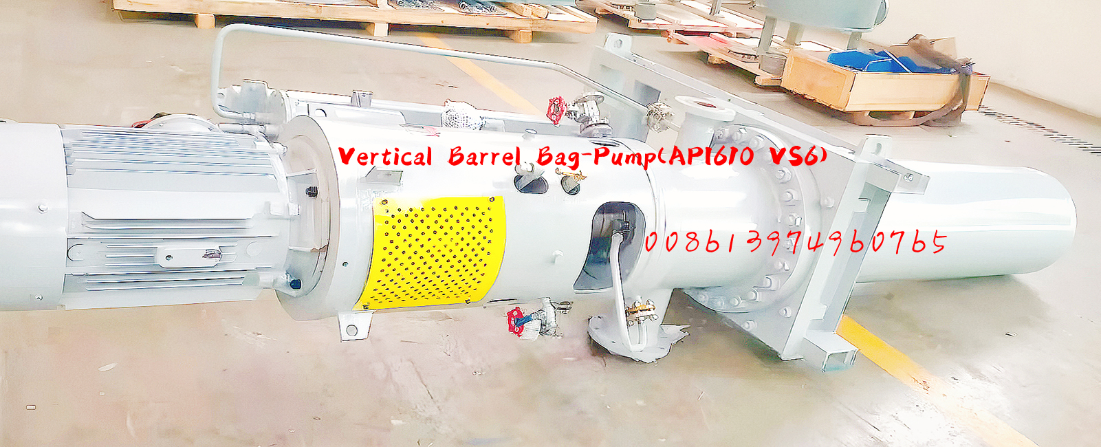
Vertical Cryogenic Process Pump is a vertical external simplified pump with three structural forms.
(1) Type A-Initial Dual-suction Guide Vane Multi-stage Centrifugal Condensation Pump
(2) B-initial stage double suction helical guide vane multi-stage centrifugal condensation pump
(3) C-initial stage double suction helical oblique flow multi-stage condensation pump

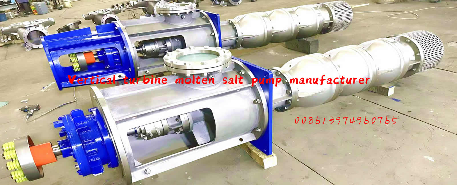
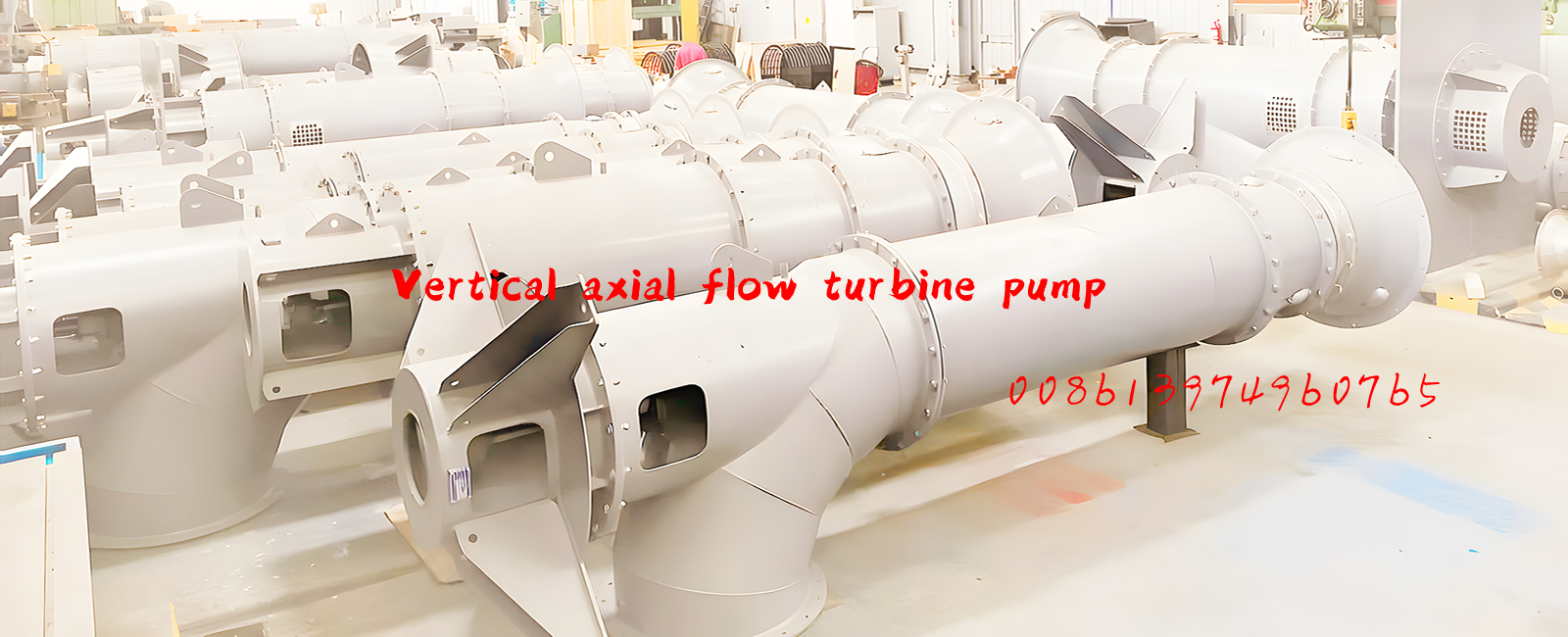
2.1 Whole structure:
Vertical Cryogenic Process Pump is a vertical double deck shell structure, and the single base is installed. For the single suction impeller or double suction impeller as a secondary form, single suction form. The suction port of the water pump can be positioned under the foundation or on the base layer, and the outlet is arranged on the foundation, and the two can be arranged at an angle of 90 DEG, 180 DEG, etc.. The inner shell part can be drawn out for maintenance and overhaul.
The axial thrust of the pump and the weight of the rotor are carried by the pump body, and the pump and the motor are connected by an elastic coupling.
From the end of the motor, the pump rotates counter clockwise.
Construction Feature


2.2 Type A-Initial Dual-suction Guide Vane Multi-stage Centrifugal Condensation Pump Structural Composition

B-initial stage double suction helical guide vane multi-stage centrifugal condensation pump Structural Composition

C-initial stage double suction helical oblique flow multi-stage condensation pump Structural Composition

2.2.1 Outer cylinder
The outer cylinder is a round cylindrical part welded by a high quality carbon steel plate or stainless steel plate. When the suction port is below the base layer, the suction port is opened on the outer cylinder. The outer cylinder is the outer pressure chamber of the pump, and the liquid can be stably introduced into the suction bell mouth. When the normal temperature pump works, the cavity is in a vacuum state, and the cavity is in a positive pressure state when the high temperature pump works.
2.2.2 Pump rotor
The pump rotor is the core part of the pump, impeller, pump shaft, shaft sleeve, sleeve, keys and other parts, the increase of imports of impeller flow area to improve the anti cavitation performance of the pump.
Impeller: the impeller converts the mechanical energy of the prime mover into water by rotating it at high speed.
Pump shaft: the main transmission torque, coupled with the motor through the flexible coupling.
The pump shaft and impeller are connected by a key and a round nut, and the key transfers the torque, and the round nut is positioned in an axial direction.
The pump shaft and the pump shaft are connected by a sleeve coupling, and the utility model has the advantages of good neutrality and convenient assembly and disassembly.
2.2.3 Suction bell
The suction bell outer cylinder in water evenly and stably into the impeller, is arranged inside the guide bearing chamber is connected by ribs. Guide bearing, impeller sealing ring is installed on the suction bell inside. The suction bell is connected with the inlet section by the stud nut.
2.2.4 Guide vane
The function of the guide vane is to change the kinetic energy of the liquid into the pressure energy and guide the liquid flowing out of the impeller into the lower impeller or the outlet section with the minimum loss. The guide vane is sheathed on the guide blades.
2.2.5 Middle part
The guide vanes are arranged in the middle section, and each middle section is positioned by a stopper, and is fastened with the water inlet section and the water outlet section through the bar. Each secondary impeller seal ring is installed in the part, and the middle part of the lug boss prevents the guide vane from rotating.
2.2.6 Effluent section and lifting pipe
The liquid in the pump is drawn out uniformly, and the guide bearing is installed in it.
2.2.7 Curved pipe
The water outlet pipe is welded by the straight pipe section, the transverse pipe section and the supporting plate, etc. when the suction port is above the base layer, the suction port is opened on the water outlet bent pipe, and the main shaft passes through the center of the part. The liquid flowing from the suction pipe passes through the part and enters the pump outside the pressure pipe horizontally. A gas discharge opening is arranged on the water outlet elbow so as to discharge the gas in the outer cylinder into the condenser or the pump body. The motor seat is installed on the water outlet bend pipe, and the shaft seal part and the balance device are installed in the water outlet bent pipe.
2.2.8 Guide bearing
The guide bearing plays the role of supporting the pump shaft in a radial direction, and the lubricating fluid is the liquid of the pump itself.
2.2.9 Mechanical seal parts
The water pump can be made of a container type mechanical seal, the machine seal is connected with the machine sealing body, and the flushing water needs to be connected, and the water source can be connected with the cooling water, and can also be extracted from the pump out of the jellyfish tube.
2.2.10 Thrust bearing parts
The water pump with deep groove ball bearings and thrust roller bearing residual axial force, oil lubrication, cooling pipe external can also leads to cooling water cooling water pipe from the pump, the rotor with the adjusting nut to adjust thrust bearing parts in ascension.
2.2.11 Coupling parts
The two shafts of the pump are connected by a sleeve coupling, and the elastic coupling is used between the rotor of the pump and the motor.
3. Assembly and disassembly of pumps
When the pump is discharged from the factory, random data such as assembly drawings and assembly drawings should be carefully read when disassembling or assembling.
3.1 Disassembly
3.1.1 Disassemble Pipeline
Before disassembling the pump body, the small piping should be disassembled.
(1) The small pipes to be dismantled include balancing pipes, degassing pipes, cooling chamber pipes, shaft sealing water sealing pipes or machine sealing flushing pipes, and oil pipes in thrust bearing components;
(2) When disassembling piping, marking should be made at the joint of piping to facilitate assembly.
(3) After the piping is dismantled, in order to prevent foreign bodies from entering, the piping mouth shall be sealed with plastic cloth, etc.
(4) Removal of fasteners should be properly kept in case of loss.
3.1.2 Remove the coupling pin
Remove the pins, nuts and washers in the elastic coupling components.
3.1.3 Removal of motor and motor base
(1) Confirm that the power supply is off and remove the power cable;
(2) Remove the connecting studs, nuts and washers between the motor and the motor base;
(3) Lifting the motor and moving it to the temporary storage place;
(4) A support frame should be set up in the motor storage area to ensure that the lower end of the motor coupling does not touch the ground and the motor does not tip over.
(5) Remove the motor base.
3.1.4 Dismantling Pump Coupling
(1) Pull out pump coupling;
(2) Coating anti-rust oil on shaft hole of coupling.
3.1.5 Removal of thrust bearing components
(1) Remove the locking nut after turning out the countersunk head screw in the locking nut;
(2) Remove the bearing cover and the oil seal ring installed in the inner hole of the bearing;
(3) Remove the cooling chamber cover;
(4) After releasing the lubricating oil in the inner cavity of the bearing, the oil-proof barrel is removed from below.
(5) Remove deep groove ball bearings, transmission sleeves and thrust self-aligning roller bearings;
(6) Remove the bearing body.
3.1.6 Disassemble Shaft Seal Components
(1) Remove the bearing seat;
(2) Remove the packing cap, packing and packing ring (when the shaft seal is packed);
(3) Remove the assembled mechanical seal (when the shaft seal is a mechanical seal);
(4) Remove the packing or mechanical seal;
(5) Remove the cooling chamber cover;
(6) Remove the guide bearing in the filler (seal) and the key to prevent rotation.
3.1.7 Dismantling Balance Drum, etc.
(1) Remove the upper axle sleeve;
(2) Remove the half-stop ring and balance drum;
(3) Remove the balance drum sleeve.
3.1.8 Removal of Pump Body
(1) Remove the connecting nut of the water bend pipe and the outer cylinder;
(2) The pump body is lifted from the outer barrel body (since the positioning screw plays a positioning role under the outer barrel body, the pump body must be lifted vertically and gently when lifting the pump body);
(3) The opening part of the outer barrel body should be provided with a well cover to prevent people or foreign bodies from falling into the wellbore.
3.1.9 Pump Body Placement
The pump body is hoisted and transported to the disassembly site for horizontal disassembly.
3.1.10 Removal of outlet elbow and riser
(1) Remove the connecting bolts of the outlet water elbow and the guide bearing body and the upper water pipe, and hoist the water elbow horizontally.
(2) Horizontal lifting of the guide bearing body and the riser pipe;
(3) Remove guide bearings and anti-rotation keys installed in guide bearings;
(4) In order to prevent the bending of the pump shaft, the shaft outside the pump body needs to be supported by square wood.
3.1.11 Remove sleeve coupling components
(1) Remove the connecting bolts between the thrust clasp and the sleeve coupling body and remove the thrust clasp;
(2) Make the sleeve coupling body move outward along the upper main axis until the connecting clasp in the sleeve coupling body is completely exposed, and then remove the connecting clasp;
(3) Remove the sleeve coupling body from the upper spindle.
3.1.12 Remove the riser (if any)
Horizontally hoist the lower guide bearing body and the lower riser, and remove the guide bearing, retaining ring and anti-rotation key in the guide bearing body.
Removal of 3.1.13 Inner Shell and Rotor Components
(1) Remove the connecting nut of the threading bar and the threading bar (for type A and B pumps);
(2) Remove the connecting studs on the suction bell mouth, remove the guide bearings, retaining rings and anti-rotation keys in the suction bell mouth and its inner hole, and remove the sealing rings;
(3) Unscrew the small round nut at the end of the shaft and remove the sleeve and the first impeller (double suction type);
(4) Remove the first guide vane (for Class A pumps)
(5) For Class A and B pumps, remove the cover plate, remove impeller, guide vane, shield and middle section. For Class C pumps, the last stage guide vane body, intermediate bushing, half baffle ring and impeller are removed from the other end.
(6) For Class A and B pumps, the last guide vane and outlet section are removed; for Class C pumps, the guide vane body, intermediate shaft sleeve, split half baffle ring and impeller are removed.
(7) The parts removed above shall be placed on the flat plate without damage or loss.
Assembly of 3.2A.B.C Vertical Multi-stage Cylinder-bag Condensation Pump
The assembly sequence is contrary to the disassembly sequence, but the following points should be noted:
3.2.1 Overall
(1) O-rings and gaskets shall be assembled in accordance with the requirements of random assembly drawings to determine the location, quantity, specifications and materials of the assembly, and note that no scratches shall be found on the surface of the seals, let alone omitted during installation;
(2) Lubricants (such as molybdenum disulfide, etc.) should be applied to all moving parts, key surfaces and bolt threads.
(3) Attention should be paid to the dropping of key and other small parts.
(4) When assembling, foreign bodies should be prevented from entering the pump, especially tools and so on.
(5) The positioning screw on the sleeve shall be screwed in after the sleeve is fully installed and then riveted or spot welded.
(6) Four positioning screws on the outer cylinder body have been welded firmly on the outer cylinder body and can not be disassembled.
Confirmation of 3.2.2 Pump Foundation Level
Before the outer cylinder is hoisted into the pump pit, it is necessary to ensure that the level of the installation foundation meets the requirements.
3.2.3 Filling (for packing seal)
(1) Check whether the size of the new packing is accurate, and measure whether the corresponding size of the packing chamber is in accordance with the packing. When replacing fillers, it is important to remember that the size of fillers can not be calculated according to the old ones removed.
(2) When cutting the filler, the filler should be carefully wound around the rod (tube) with the same outer diameter as the upper sleeve. In order to ensure that the packing can be cut accurately, two parallel lines can be gently drawn on the surface of the packing, and then the packing can be cut off.

(5) After filling, screw on the nut to adjust the packing cap, so that the leakage water is in a continuous state of leakage.
Installation of 3.2.4 O-ring
(1) Installation form of O-ring: U+25CB-ring in condensation pump series belongs to fixed seal, the main sealing forms are as follows:

When O-ring is bonded by rubber strip, the following points should be paid attention to:
1. The cutting length of rubber strip should be measured according to the actual installation position.
2. The notch should be 45 degrees from the rubber strip axis.
3. If there are burrs on the surface of rubber strip, it should be carefully repaired.
4. Installation of A.B.C Vertical Multi-stage cylinder-bag condensation pump
Whether the installation quality is good or not will have a significant impact on the operation of the pump, we must be serious and careful.
Foundation of 4.1 Pump
(1) The foundation of the pump should be firm and firm;
(2) The height of the outer cylinder is adjusted by inclined pad iron between the outer cylinder body and the foundation, so that the upper plane of the outer cylinder body is on the horizontal plane, and the level is checked by the level meter. The tolerance of the level is 0.05 mm/1000 mm.
(3) After positioning the outer cylinder body, cement mortar is poured into the bolt hole of the foot from below the floor, and the bolt nut of the foot can be tightened after the cement mortar is dried and solidified.
(4) Cement mortar must completely fill the cavity under the floor.
4.2 Pipeline Connection
When connecting pipes and valves, if the tightening force of connecting bolts is too large or uneven, the additional moment will cause deformation of the pump body and bad internal contact, which directly affects the normal operation of the pump. Therefore, after the installation of valves and pipes, the unit level should be corrected again.
4.3 No foreign body remains in the pipeline
In the process of installation, foreign bodies should not fall into the pump, otherwise the pump will be easily damaged.
Installation of 4.4 Inhalation Pipeline
Inhalation pipeline should be as short as possible and the bend of pipeline should be far away from the flange of pump inlet. When connecting suction pipeline and pump inlet flange, it is necessary to ensure that the joint surface is completely sealed to prevent air from entering the pump.
Installation of 4.5 Motor
(1) Pump coupling and motor coupling are installed on the pump shaft and motor shaft respectively, and the motor is hoisted on the motor base.
(2) Check the alignment of the two couplings: Fix the dial base on the pump couplings to check the motor couplings'runout, the allowance is 0.08mm. Check the end clearance difference between the two couplings (see table below for the end clearance value), the allowance is 0.10 mm. If the above measured values are out of tolerance, the adjusting bolts in the four adjusting seats on the motor seat can be adjusted, and thin copper sheets can be padded between the motor connecting flange and the motor seat to make the jump value meet the requirements.
Coupling Outer Diameter(mm) | 170 | 190 | 220 | 260 | 330 | 410 | 640 |
End clearance of two coupling (mm) | 4 | 4 | 4 | 5 | 6 | 7 | 8 |
(3) After the coupling is qualified for neutrality, the pin of the connecting column is installed, and then the motor is fastened with bolts or studs.
4.6 Rotor Lifting Height
The residual axial thrust of the pump is borne by the thrust aligning roller bearing in the thrust bearing component of the upper part of the pump. The lifting height of the rotor is realized by adjusting the locking nut in the part.
(1) Loosen the locking nut, so that the rotor parts slowly and freely fall until they no longer fall;
(2) Slowly tighten the locking nut so that the rotor can not rise again. Measure the total height of the rotor (generally about 10 mm);

5. Starting, running and stopping
5.1 Inspection preparation before starting
(1) clean up the site and check if the anchor bolts are loose;
(2) whether the inlet valve of the pump is fully open;
(3) is the pump filled with liquid?;
(4) open the exhaust valve on the condenser, completely exhaust the gas in the pump;
(5) is the outlet valve of the pump closed?;
(6) whether the motor steering meets the requirements;
(7) whether the coupling pin is loose;
(8) whether the cooling water of the bearing cooling gland and the seal cooling water are opened, and whether the flushing water pipe of the machine is unblocked or not;
(9) motor and other electrical appliances and instruments are normal;
(10) the rotor of the rotary pump should be able to rotate evenly and without clamping or unilateral.
5.2 Start
(1) turn off the outlet valve and the pressure gauge cock;
(2) starting motor;
(3) when the motor speed reaches the rated value, open the pressure gauge cock, and gradually open the outlet valve, adjust the outlet pressure to the required working conditions. When the outlet valve is closed, the pump shall not run continuously for more than 2 minutes;
5.3 Run
(1) the temperature of the rolling bearing shall not exceed 35 degrees above the ambient temperature, and the maximum temperature shall not exceed 75 degrees centigrade;
(2) in the starting and operation process, we must pay attention to observe instrument readings, bearing temperature, vibration and noise of pump set is normal, if abnormal situation occurs, should be dealt with immediately;
(3) check the cooling water and flushing water regularly, and do not allow the water to be cut off during the operation;
(4) pay attention to bearing temperature;
(5) keep the thrust bearing parts lubrication oil level in normal position, should not be too high or too low, otherwise, should be put oil or refueling. Under normal circumstances, 200 hours after the first operation, you should replace the new oil;
(6) no continuous operation is allowed under the design flow of less than 30%. If the operation must be continuous under this condition, the bypass pipe shall be installed at the outlet of the pump, and the excess flow shall be introduced into the pump inlet. It is not allowed to operate continuously at higher than 120% design flow, so as to avoid cavitation and motor over power;
(7) strictly increase the rated speed of water pump.
5.4 stop
(1) turn off the pressure gauge cock;
(2) gradually close the exit valve;
(3) cut off the power supply;
(4) when the pump stops turning completely, turn off the cooling water and the valve on the small pipe;
(5) if the pump is used for a long time, the pump should be removed, cleaned, oiled, and kept in storage.
6 Maintenance and repair
6.1 Running diary and Management file
(1) running diary
Record the operation of the pump as a basis for formulating the pump operation plan.
Running diary should include at least the detection time, open (stop) machine time, pressure gauge readings, current, voltage, frequency, speed, vibration, noise, environment temperature, bearing temperature, seal leakage, entrance pressure (vacuum) data.
(2) management archives;
Management records should be the pump and the prime mover of the factory time, manufacturers, the main performance parameters, maintenance records.
6.2 maintenance
The correct maintenance operation is of great significance to the pump in the best state of operation, fully play its role, improve the service life of the pump, and avoid accidents. Frequent inspection and maintenance is one of the most important methods to avoid over use and take preventive measures.
(1) routine maintenance inspection items:
A.Shut off the pressure gauge cock when the A. pump is stopped;
B.check cooling water, sealing water, water supply system, piping circuit and pump for leakage;
C. check all kinds of meters;
D. periodically measure the vibration value of pump set, and pay attention to the noise;
E. keep the unit clean;
F. make running records.
(2) monthly inspection items;
A. check and adjust the pump and motor to ensure concentricity;
B. check lubricating oil, cooling water and sealing water;
C. measuring vibration and noise of pump unit;
D. on the long time of the pump (such as standby pump), starting a running time, not less than 5 minutes; conditions for the restricted case of the manual turning.
(3) annual inspection items;
A. inspect the worn parts of the rotating parts;
B. check the clearance between the impeller and the sealing ring;
C. check the impeller, guide vanes, guide vanes and other parts of the flow channel of cavitation and erosion;
D. inspect the wear of bearings and bushings.
6.3 Repair
Pump should be disassembled and repaired when necessary (vibration or noise abnormal, bearing temperature is too high, flow head obviously decreased, etc.). For continuous running pumps, a regular overhaul shall be carried out every year.
(1) the maintenance experience shall be recorded in detail during the maintenance work for reference during the next maintenance;
(2) spare parts are prepared in advance. When purchasing spare parts, the name, material and quantity of the spare parts shall be clearly stated, and the pump type, name, date of manufacture and serial number of the factory shall be clearly stated;
(3) the demolition by the reverse assembly sequence, after the demolition of the parts of the rust removing and re coating;
(4) check the clearance between the impeller and the sealing ring. The replacement criteria are shown in the following table (reference):
Nominal diameter (mm) | ~125 | ~160 | ~200 | ~250 | ~315 | ~400 | ~500 |
Maximum allowable diameter clearance (mm) | 1.1~1.8 | 1.2~2.0 | 1.3~2.2 | 1.5~2.5 | 1.7~2.8 | 1.9~3.1 | 2.1~3.5 |
(5) check the clearance between the guide bearing and the axle sleeve. The replacement criteria are shown in the following table (reference):
Nominal diameter (mm) | ~60 | ~80 | ~100 | ~120 | ~140 | ~160 | ~180 |
Maximum allowable diameter clearance (mm) | 0.4~0.8 | 0.5~0.9 | 0.6~1.0 | 0.7~1.2 | 0.8~1.3 | 0.9~1.4 | 1.0~1.5 |
(6) check the wearing of the axle sleeve, and change the diameter direction from 1 to 2mm in case of wear;
(7) inspect the wear of the impeller, guide vanes and other parts;
(8) replacement of seals (O ring, rubber pad, etc.);
(9) assemble according to assembly sequence. After the rotation of the pump rotor assembly, should be balanced.
7. Possible Troubles & Remedies
TROUBLES | CASES | Solution |
Insufficient flow
No water
| 1. Inhalation side or outlet side or impeller with debris blockage 2. Overwear of sealing ring or damage of impeller 3. Steering discrepancy 4. Too low speed 5. Air inhalation 6. Installation head is too high 7. The pump is not filled with conveying liquid.
| 1. Clean up blockages in filter, suction port, impeller, guide vane and discharge valve system. 2. Replacement of damaged parts 3. Correction steering 4. Measure voltage and frequency, check motor 5. Exhaust the gas in the inhalation pipe and check the inhalation pipe 6. Reduce system resistance and adjust operating conditions 7. Inspection of Inhalation Pipeline System |
Unable to start | 1. Faults of motor or power supply system 2. Foreign bodies in rotor components 3. Bearings are stuck 4. Starting conditions are not satisfied
| 1. Maintenance of motor or power supply system 2. Cleaning rotor components 3. Cleaning or replacing bearings 4. Conditions to be met for inspection
|
Overload
| 1. Bearing damage 2. Foreign body in pump 3. Friction between impeller and seal ring 4. Over-compacted packing 5. Excessive speed 6. Pump running beyond allowable operating range under large flow rate 7. One-phase circuit break of power supply line and single-phase operation of motor
| 1. Replacement of bearings 2. Removal of foreign bodies 3. Repair or replace impellers or sealing rings 4. Relax packing 5. Check voltage, frequency, motor and adjust them. 6. Close the outlet gate valve 7. Maintenance of power supply lines |
Abnormal vibration and noise
| 1. Cavitation of pump 2. Excessive unbalanced weight of impeller 3. Pump and motor axles are not centrifugal or axle bending 4. Foot bolt loosening 5. Bearing damage 6. Excessive wear of guide bearings and bushes 7. The influence of discharge pipeline | 1. Increase the suction level or close the outlet gate valve 2. Impeller rebalancing 3. Concentricity of correction axis, alignment axis 4. Tighten the anchor bolts 5. Replacement of bearings 6. Replacement of guide bearings and bushes 7. Check the discharge line |
Bearing heating
| 1. Poor assembly and excessive eccentricity of axle center 2. Bearing damage 3. Less or less oil in bearings | 1. Check the radial runout and correct it. 2. Replacement of bearings 3. Supplementary lubricants |
TEL:008613974960765,008618507312158
Address:Xiangyin County Industrial Park, Yueyang City, Hunan Province, China
E-mail:sale@ljpump.net

Marketing WeChat

WeChat Official Account
Copyright © 2004-2024 Hunan Perfect Industry Co.,Ltd All Rights Reserved. Sitemap Vertical Turbine Pump Manufacturers
Copyright © 2008-2024 Hunan Perfect Industry Co.,Ltd All Rights Reserved.
+8613974960765
Wechat QR code